


What Our Customers Are Saying
SKU
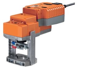
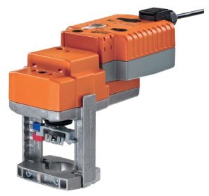
NVK24A-3-RE
NVK24A-3-RE Supercap Globe Valve Actuator Retrofit, AC 24 V, 150 s - Belimo | ideal for globe valves
£645.12
£537.60
On request
Next Supplier Stock Update: 07/06/2026
Manuals & Datasheets
| DATASHEET |
| Product type | Actuator |
| IP rating | IP54 |
| Manufacturer | Belimo |
| Power Supply | 24Vac/Vdc |
| Torque | 1000 N |
| Running time | 140 to 150 sec |
| Ideal for | globe valves |
We provide Free Delivery and Next 1-2 Day Delivery for all Belimo Actuators that are in stock at iacs.
The Belimo NVK24A-3-REis a type of Actuator used to control valves in HVAC systems and applications.
The Torque force applied by the NVK24A-3-RE is 1000 N.
The power supply requested for this Valve Actuator is 24Vac/Vdc.
This Belimo component can be used with Globe Valves.
Find at IACS the ideal Belimo Actuator compatible with your system at the best price.
If you are unsure about size or installation, refer to the Belimo custom datasheet above or message iacs to receive special instructions and a custom quote.
NVK24A-3-RE Supercap Globe Valve Actuator Retrofit, AC 24 V, 150 s
- 1000 N, 20 mm,
- AC 24 V, 3-point
- Actuating time motor 150 s / 20 mm
- IP 54, Manual override temporary
- Universal valve adapter separately
- Connection terminal without cable
- Stroke direction / closing point selectable (top/bottom)
- Power-Off-Position adjustable
Mode of operation: The actuator moves the valve to the desired operating position at the same time as the integrated capacitors are loaded. Interrupting the supply voltage causes the valve to be moved to the selected emergency setting position (POP) by means of stored electrical energy.
Pre-charging time (start up): The capacitor actuators require a pre-charging time. This time is used for charging the capacitors up to a usable voltage level. This ensures that, in the event of an electricity interruption, the actuator can move at any time from its current position into the preset emergency setting position (POP). The duration of the pre-charging time depends mainly on how long the power was interrupted.

Delivery condition (capacitors): The actuator is completely discharged after delivery from the factory, which is why the actuator requires approximately 20 s pre-charging time before initial commissioning in order to bring the capacitors up to the required voltage level.
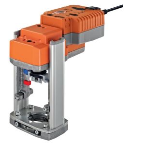
Installation on third-party valves: The retrofit actuators for installation on a wide range of valves from various manufacturers are comprised of an actuator, bracket, universal valve neck adapter and universal valve stem adapter. Adapt the valve neck and valve stem to begin with, then attach the retrofit bracket to the valve neck adapter. Now fit the retrofit actuator into the bracket and connect it to the valve. Whilst taking the position of the valve closing point into account, secure the actuator to the bracket and then conduct the commissioning process. The valve neck adapter/actuator can be rotated through 360° on the valve neck, provided it is permitted by the size of the installed valve.
Installation on BELIMO valves: Please use standard actuators from Belimo for installation on Belimo globe valves. The installation of retrofit actuators on Belimo globe valves is technically possible.
Manual override: Manual control with push-button possible - temporary. The gear is disengaged and the actuator decoupled for as long as the button is pressed. The stroke can be adjusted by using a hexagon socket screw key (4 mm), which is inserted into the top of the actuator. The stroke spindle extends when the key is rotated clockwise.
High functional reliability: The actuator is overload protected, requires no limit switches and automatically stops when the end stop is reached.
Position indication: The stroke is indicated mechanically on the bracket with tabs. The stroke range adjusts itself automatically during operation.
Home position: Factory setting: Actuator spindle is retracted.
Direction of stroke switch: When actuated, the direction of stroke switch changes the running direction in normal operation. The direction of stroke switch has no influence on the emergency setting position (POP) which has been set.
Rotary knob emergency setting position: The «Emergency setting position» rotary knob can be used to adjust the desired emergency setting position (POP). The POP range is in reference to the maximum height of stroke of the actuator. In the event of an electricity interruption, the actuator will move into the selected emergency setting position, taking into account the bridging time (PF) of 2 s which was set ex-works.
Electrical data:
- Nominal voltage AC 24 V
- Nominal voltage frequency 50/60 Hz
- Nominal voltage range AC 19.2...28.8 V
- Power consumption in operation 2.5 W
- Power consumption in rest position 1.5 W
- Power consumption for wire sizing 6 VA
- Connection supply / control Terminals 4 mm² (cable Ø 4...10 mm)
- Parallel operation Yes (note the performance data)
Functional data:
- Actuating force 1000 N
- Setting emergency position (POP) Actuator spindle retracted / extended,
- adjustable (POP rotary button)
- Manual override Gear disengagement with push-button
- Nominal stroke 20 mm
- Actuating time 150 s / 20 mm
- Actuating time emergency control function 35 s / 20 mm
- Sound power level motor max. 56 dB(A)
- Sound power level emergency setting position max. 60 dB(A)
- Position indication Mechanically, 5...20 mm stroke
Safety:
- Protection class IEC/EN III Safety extra-low voltage
- Degree of protection IEC/EN IP54
- EMC CE according to 2004/108/EC
- Certification IEC/EN IEC/EN 60730-1 and IEC/EN 60730-2-14
- Mode of operation Type 1.AA
- Rated impulse voltage supply / control 0.8 kV
- Control pollution degree 3
- Ambient temperature 0...50°C
- Non-operating temperature -40...80°C
- Ambient humidity 95% r.h., non-condensing
- Maintenance Maintenance-free
Weight: Approx. 2.8 kg
Terms Abbreviations: POP = Power off position / emergency setting position, CPO = Controlled power off / controlled emergency control function, PF = Power fail delay time / bridging time
Customers Also Bought