What Our Customers Are Saying
SKU
NKQ24A-SR
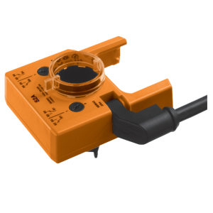
NKQ24A-SR POP Damper Actuator , 6 Nm, AC/DC 24 V, 4 s - Belimo
£493.92
£411.60
On request
Next Supplier Stock Update: 06/06/2026
Manuals & Datasheets
| DATASHEET |
| Product type | Actuator |
| IP rating | IP54 |
| Manufacturer | Belimo |
| Power Supply | 24Vac/Vdc |
| Torque | 6 Nm |
| Running time | Quick (2.5 to 20 sec) |
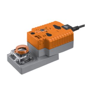
NKQ24A-SR POP damper actuator , 6 Nm, AC/DC 24 V, 4 s
- 6 Nm, 4 s, fast running, 95°
- AC/DC 24 V, 4 s, modulating
- Running time POP 4 s / 95°
- Power-Off-Position adjustable
- IP 54,
- Control DC 0...10 V
- Operating range DC 2...10 V
- Connection cable length = 1 m
- Direction of rotation reversible (right/left)
- Spindle driver universal spindle clamp
Mode of operation: The actuator moves the damper to the desired operating position at the same time as the integrated capacitors are charged. Interrupting the supply voltage causes the damper to be rotated back into the emergency setting position (POP) by means of stored electrical energy. The actuator is connected with a standard modulating signal of DC 0...10V and drives to the position defined by the positioning signal. Measuring voltage U serves for the electrical display of the damper position 0...100% and as slave control signal for other actuators.
Pre-charging time (start up): The capacitor actuators require a pre-charging time. This time is used for charging the capacitors up to a usable voltage level. This ensures that, in the event of an electricity interruption, the actuator can move at any time from its current position into the preset emergency setting position (POP). The duration of the pre-charging time depends mainly on following factors: – Duration of the electricity interruption – PF delay time (bridging time)

Delivery condition (capacitors): The actuator is completely discharged after delivery from the factory, which is why the actuator requires approximately 20 s pre-charging time before initial commissioning in order to bring the capacitors up to the required voltage level.
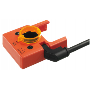
Simple direct mounting: Simple direct mounting on the damper spindle with an universal spindle clamp, supplied with an anti-rotation device to prevent the actuator from rotating.
Manual override: Manual control with push-button possible - temporary. The gear is disengaged and the actuator decoupled for as long as the button is pressed.
High functional reliability: The actuator is overload protected, requires no limit switches in intermediate positions and automatically stops when the end stop is reached (at rest).
Adjustable angle of rotation: Adjustable angle of rotation with mechanical end stops. A minimum permissible angle of rotation of 30° must be allowed for.
Home position:The first time the supply voltage is switched on, i.e. at the time of commissioning, the actuator carries out an adaption, which is when the operating range and position feedback adjust themselves to the mechanical setting range. The detection of the mechanical end stops enables a gentle approach to the end positions, thus protecting the actuator mechanics. The actuator then moves into the position defined by the positioning signal.
Direction of rotation switch: When actuated, the direction of rotation switch changes the running direction in normal operation. The direction of rotation switch has no influence on the emergency setting position (POP) which has been set.
Adaption and synchronisation: An adaption can be triggered manually by pressing the “Adaption” button. Both mechanical end stops are detected during the adaption (entire setting range). Automatic synchronisation after pressing the gear disengagement button is configured. The synchronisation is in the home position (0%). The actuator then moves into the position defined by the positioning signal.
Emergency setting position (POP) rotary knob: The «Emergency setting position» rotary knob can be used to adjust the desired emergency setting position (POP) between 0 and 100% in 10% increments. The rotary knob refers only to the adapted angle of rotation range between 30 and 95°. No set Min or Max values are observed. In the event of a electricity interruption, the actuator will move into the selected emergency setting position (POP), taking into account the bridging time that has been set.
Electrical data:
- Nominal voltage AC/DC 24 V
- Nominal voltage frequency 50/60 Hz
- Nominal voltage range AC 19.2...28.8 V / DC 21.6...28.8 V
- Power consumption in operation 11 W
- Power consumption in rest position 3 W
- Power consumption for wire sizing 22 VA
- Power consumption for wire sizing note Imax 20 A @ 5 ms
- Connection supply / control Cable 1 m, 4 x 0.75 mm²
- Parallel operation Yes (note the performance data)
Functional data:
- Torque motor Min. 6 Nm
- Positioning signal Y DC 0...10 V
- Positioning signal Y note Input impedance 100 kΩ
- Operating range Y DC 2...10 V
- Position feedback U DC 2...10 V
- Position feedback U note Max. 0.5 mA
- Setting emergency setting position (POP) 0...100%, adjustable in increments of 10% (POP rotary knob on 0 corresponds to left end stop)
- Position accuracy ±5%
- Direction of motion motor Selectable with switch 0 / 1
- Direction of motion note Y = 0 V: At switch position 0 (ccw rotation) / 1 (cw rotation)
- Direction of motion emergency control function Selectable with switch 0...100%
- Manual override Gear disengagement with push-button
- Angle of rotation Max. 95°
- Angle of rotation note can be limited on both sides with adjustable
- mechanical end stops
- Minimum angle of rotation Min. 30°
- Running time motor 4 s / 90°
- Running time emergency control position 4 s / 90°
- Running time emergency setting position note <4 s @ 0...50°C
- Adaption setting range manual (automatic on first power-up)
- Sound power level motor 60 dB(A)
- Sound power level emergency control position 60 dB(A)
- Spindle driver Universal spindle clamp 8...26.7 mm
- Position indication Mechanically, pluggable
Safety:
- Protection class IEC/EN III Safety extra-low voltage
- Protection class UL UL Class 2 Supply
- Degree of protection IEC/EN IP54
- Degree of protection NEMA/UL NEMA 2, UL Enclosure Type 2
- EMC CE according to 2004/108/EC
- Certification IEC/EN IEC/EN 60730-1 and IEC/EN 60730-2-14
- Certification UL cULus according to UL 60730-1A, UL 60730-2-14 and CAN/CSA E60730-1:02
- Mode of operation Type 1.AA
- Rated impulse voltage supply / control 0.8 kV
- Control pollution degree 3
- Ambient temperature -30...50°C
- Non-operating temperature -40...80°C
- Ambient humidity 95% r.h., non-condensing
- Maintenance Maintenance-free
Weight: 1.4 kg
Customers Also Bought