

What Our Customers Are Saying
SKU
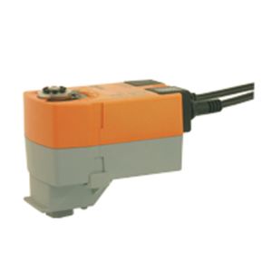
TRF24-MFT
TRF24-MFT - Belimo Spring-return actuator NC | ideal for ball valves
£244.44
£203.70
On request
Next Supplier Stock Update: 18/04/2026
Manuals & Datasheets
| DATA-SHEET |
| Product type | Actuator |
| IP rating | IP54 |
| Input Signal | 0..10 Vdc, MFT, Proportional/MFT |
| Manufacturer | Belimo |
| Power Supply | 24Vac/Vdc |
| Torque | 2.5 Nm |
| Running time | 90 to 105 sec |
| Fail Safe | Spring Return |
| Ideal for | ball valves |
At IACS we provide Free Delivery and Next 1-2 day Delivery for all the Belimo Actuators in stock.
The Belimo TRF24-MFT is an Actuator used in HVAC applications and air ventilation systems.
The Torque force applied by the TRF24-MFT is 2.5 Nm.
The power supply requested for this Rotary Actuator is 24Vac/Vdc.
Find the appropriate Belimo Actuator for your system at the greatest price at iacs.
If you have questions about size or installation, consult the Belimo custom datasheet above or send an email to iacs to get personalised guidance.
TRF24-MFT - Spring-return actuator NC
• 2 Nm, 90 s / 90°, 95°
• AC / DC 24 V, modulating, MFT
• Running time spring < 25 s
• Control DC 0...10 V (0...32 V adjustable)
• Operating range DC 2...10 V, adjustable
• Position feedback DC 2...10 V, adjustable
• Direction of rotation reversible (right/left)
• Linking active sensor, switch
Features
- Mode of operation The actuator moves the ball valve into the operating position while simultaneously charging the return spring. The ball valve is turned back into the safety position by the application of spring energy when the power supply is interrupted.Conventional operation: The actuator is controlled with a standard modulating signal of DC 0 ... 10 V and travels to the position defined by the control signal. Measuring voltage U serves for the electrical display of the damper position 0 ... 100% and as slave control signal for otheractuators.Operation on the MP-Bus: The actuator receives its digital positioning signal from the higher level controller via the MP-Bus and travels to the position defined. Connection U serves ascommunication interface and does not supply an analogue measuring voltage
- Converter for sensors Connection option for a sensor (passive or active sensor or switching contact). The MP actuator serves as an analogue/digital converter for the transmission of the sensor signal via MP-Bus to the higher level system.
- Parameterisable actuators The factory settings cover the most common applications. Input and output signals and other parameters can be altered with the MFT-H parameterising device or the BELIMO Service Tool, MFT-P.
- Simple direct mounting Simple direct mounting on the ball valve with only one screw. The mounting position in relation to the ball valve can be selected in 90°<) steps.
- High functional reliability The actuator is overload-proof, requires no limit switches and automatically stops when the end stop is reached.
- Home position When the supply voltage is switched on, the actuator automatically detects its safety position (zero initialisation). This process, which takes place with the actuator stationary, lasts approximately 15 s.
- Combination valve actuators Refer to the valve documentation for suitable valves, their permitted media temperatures and closing pressures.
• Electrical Nominal voltage AC 24 V, 50/60 Hz / DC 24 V
• Power supply range AC 19.2 ... 28.8 V / DC 21.6 ... 28.8 V
• Power consumption In operation 2.5 W @ nominal torque At rest 1 W For wire sizing 4 VA
• Connection Motor Cable 1 m, 4 x 0.75 mm2
• Parallel connection Yes
• Functional data Factory settings
• Torque (nominal torque) Motor Min. 2 Nm at nominal voltage Spring-return Min. 2 Nm
• Torque (nominal torque) Motor Min. 2 Nm at nominal voltage Spring-return Min. 2 Nm
• Control Control signal Y DC 0 ... 10 V, input impedance 100 kΩ Working range DC 2 ... 10 V
• Position feedback (measuring voltage U) DC 2 ... 10 V, max. 0.5 mA
• Uni-rotation ±5%
• Direction of rotation Motor Can be selected / Spring-return TRF24-MFT Deenergised NC, ball valve closed (A – AB = 0% TRF24-MFT-O Deenergised NO, ball valve open (A – AB = 100%)
• Direction of motion at Y = 0 V In switch position 0 or 1
• Manual override No
• Angle of rotation Max. 95°<)
• Running time Motor 90 s / 90°<) Spring return <25 s at –20 ... 50°C / max. 60 s at –30°C
• Automatic adjustment of running time, Manual triggering of the adaption by operating range and measuring signal U switching from to twice within 5 s to match the mechanical angle of rotation or with PC-Tool.
• Override control MAX (maximum position) = 100% (with reference to the effective angle of MIN (minimum position) = 0% rotation) ZS (intermediate position, AC only) = 50%
• Sound power level Motor Max. 35 dB (A) Spring return ~62 dB (A)
• Service life Min. 60’000 emergency settings
• Position indication Mechanical
• Safety Protection class III extra-low voltage
• Degree of protection IP42 in all mounting positions
• EMC CE according to 89/336/EEC
• Mode of operation Type 1 (to EN 60730-1)
• Rated impulse voltage 0.8 kV (to EN 60730-1)
• Control pollution degree 3 (to EN 60730-1)
• Ambient temperature range 0 ... +50°C
• Media temperature +5 ... +100°C (in ball valve)
• Non-operating temperature –40 ... +80°C
• Ambient humidity range 95% r.H., non-condensating (EN 60730-1)
• Maintenance Maintenance-free
• Dimensions «Dimensions» on page 5
• Weight Approx. 600 g (without ball valve)
Customers Also Bought